Wireworld
Wireworld is a cellular automaton proposed by Brian Silverman in 1987, as part of his program Phantom Fish Tank. Which; widely became popular after an article by A. K. Dewdney in the January 1990 edition of Scientific American.
If you do find any bugs please report them in the comments. I am immensely grateful to those that do so. Thank you.
RULES:
A Wireworld cell can be in one of four different states, usually numbered 0–3 in software, modeled by colors in the examples here:
empty (black),
electron head (blue),
electron tail (red),
conductor (yellow).
As in all cellular automata, time proceeds in discrete steps called generations (sometimes "gens" or "ticks") or in our case cycles/N. Cells behave as follows:
empty → empty,
electron head → electron tail,
electron tail → conductor,
conductor → electron head if exactly one or two of the neighboring cells are electron heads, otherwise remains conductor.
Wireworld uses what is called the Moore neighborhood, which means that in the rules above, neighboring means one cell away (range value of one) in any direction, both orthogonal and diagonal.
Controls:
1. Copper
2. Electron Head
3. Electron Tail
R. clear screen
WASD Move
Mouse Wheel Zoom
Escape opens menu
Space runs simulation
Install:
1. Extract WireWorld.zip
2. Run main.exe
Logic Elements:
Cycles:
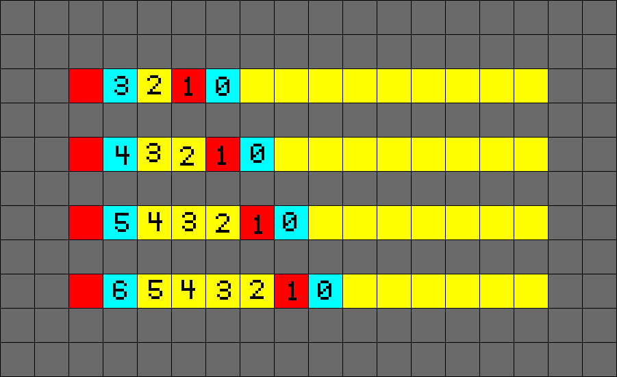
The Cycle/ Period/ N is calculated by the distance between electron heads starting at 0.
Basic Elements:
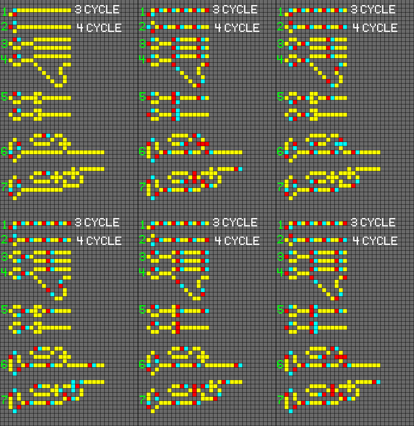
1. 3 cycle Clock
2. 4 Cycle Clock
3. Data Copying
4. Delaying Data
5. Diodes
6. Active Control Line Transistor (ANDNOT)
7. Inactive Control Line Transistor (AND)
Logic Gates:
AND Gate:
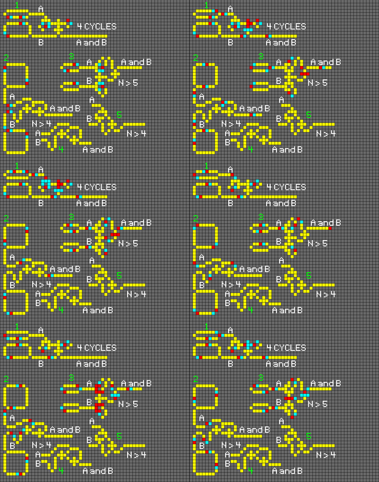
An AND gate emits an electron if there are incoming electrons at both input wires.
ANDNOT Gate:
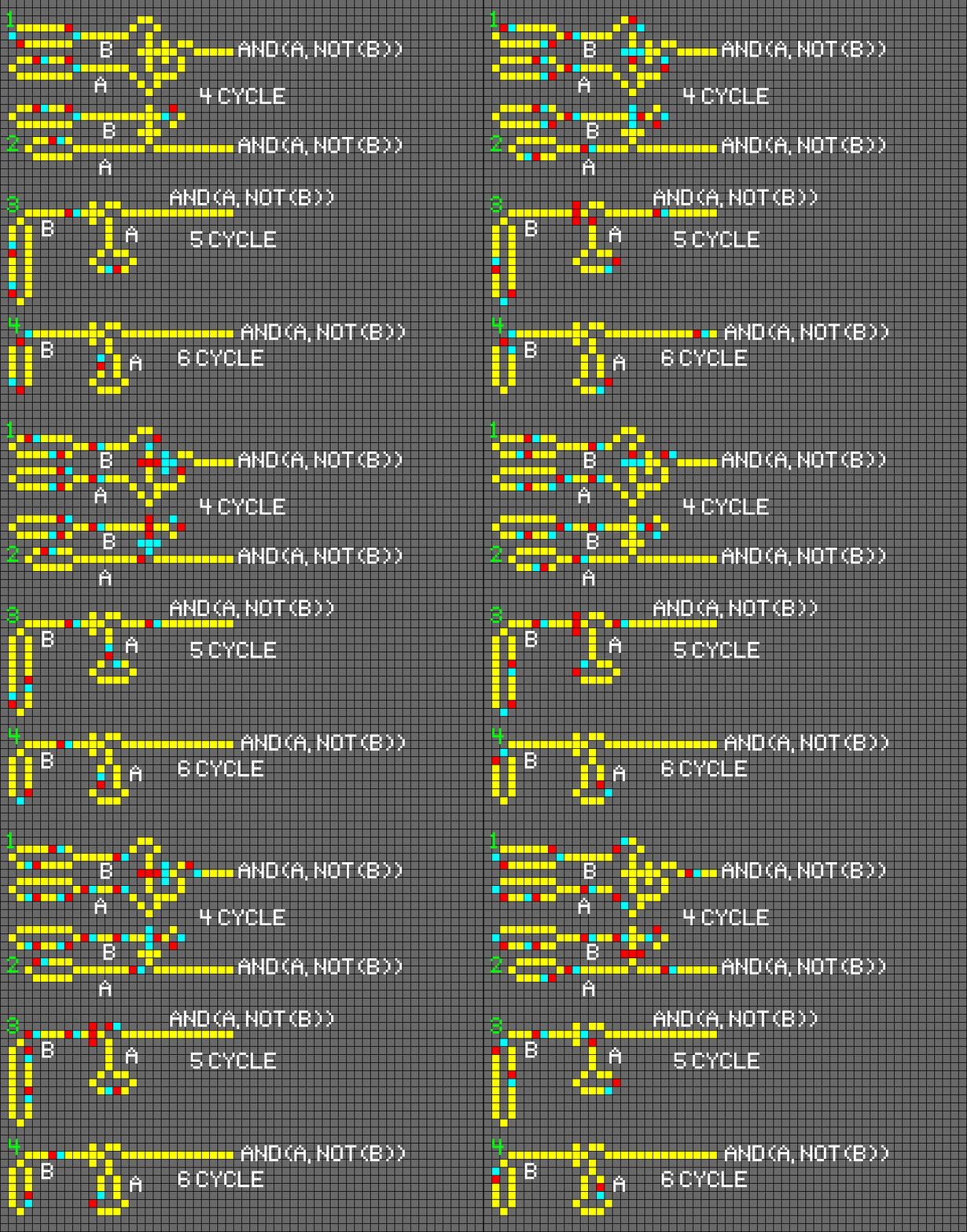
The ANDNOT gate can be seen as a data-driven NOT gate: ANDNOT(A, B) = AND(A, NOT(B)).
NAND Gate:
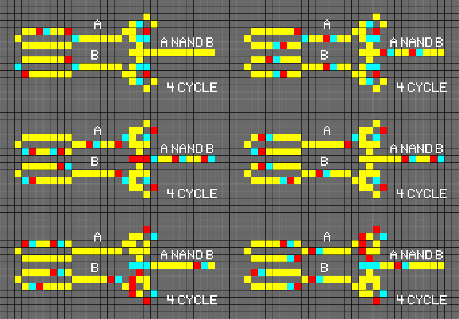
A NAND gate always emits an electron except when there are incoming electrons at both input wires.
NOT Gate:
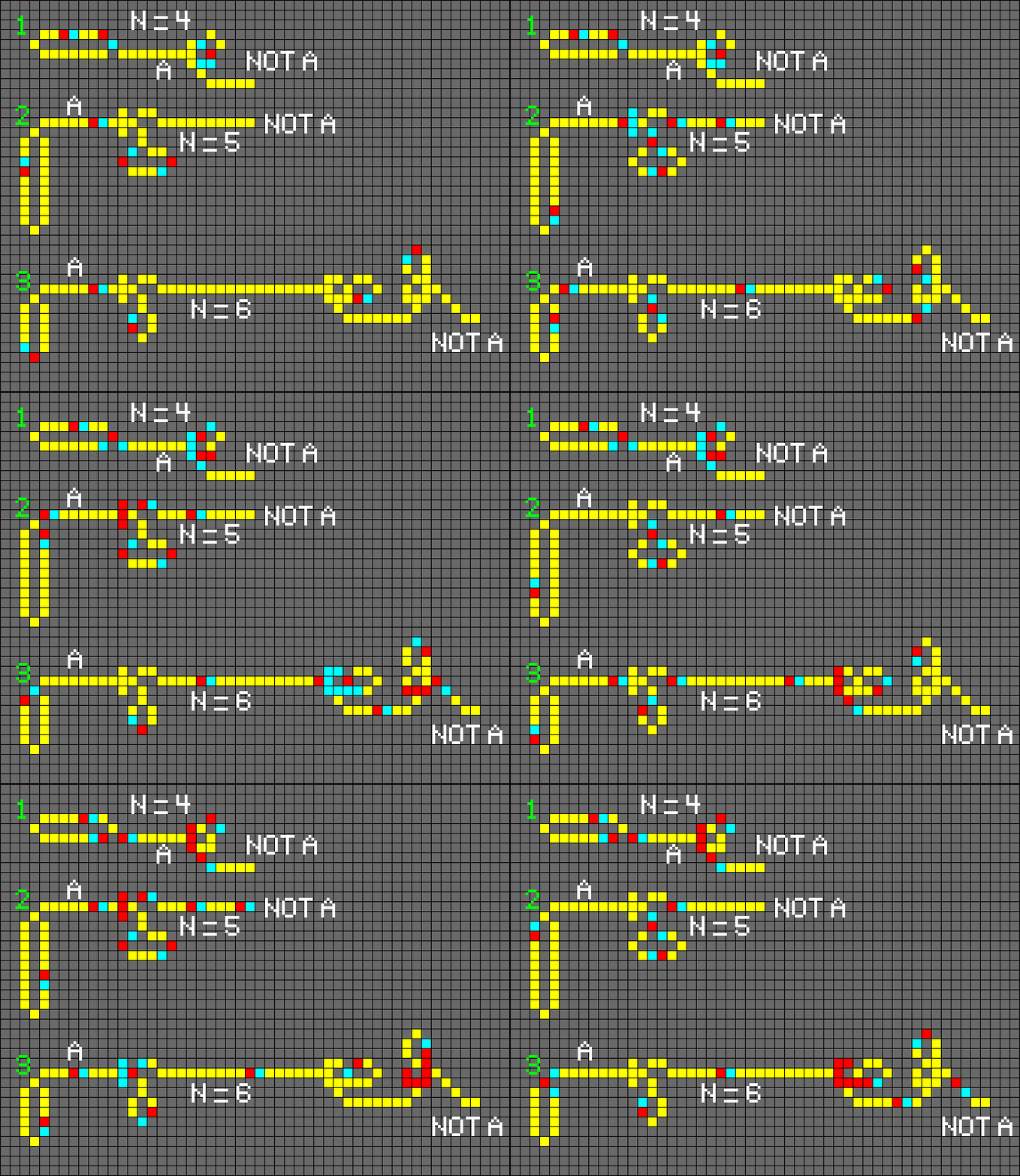
A NOT gate emits an electron if and only if there is no incoming electron.
OR Gate:
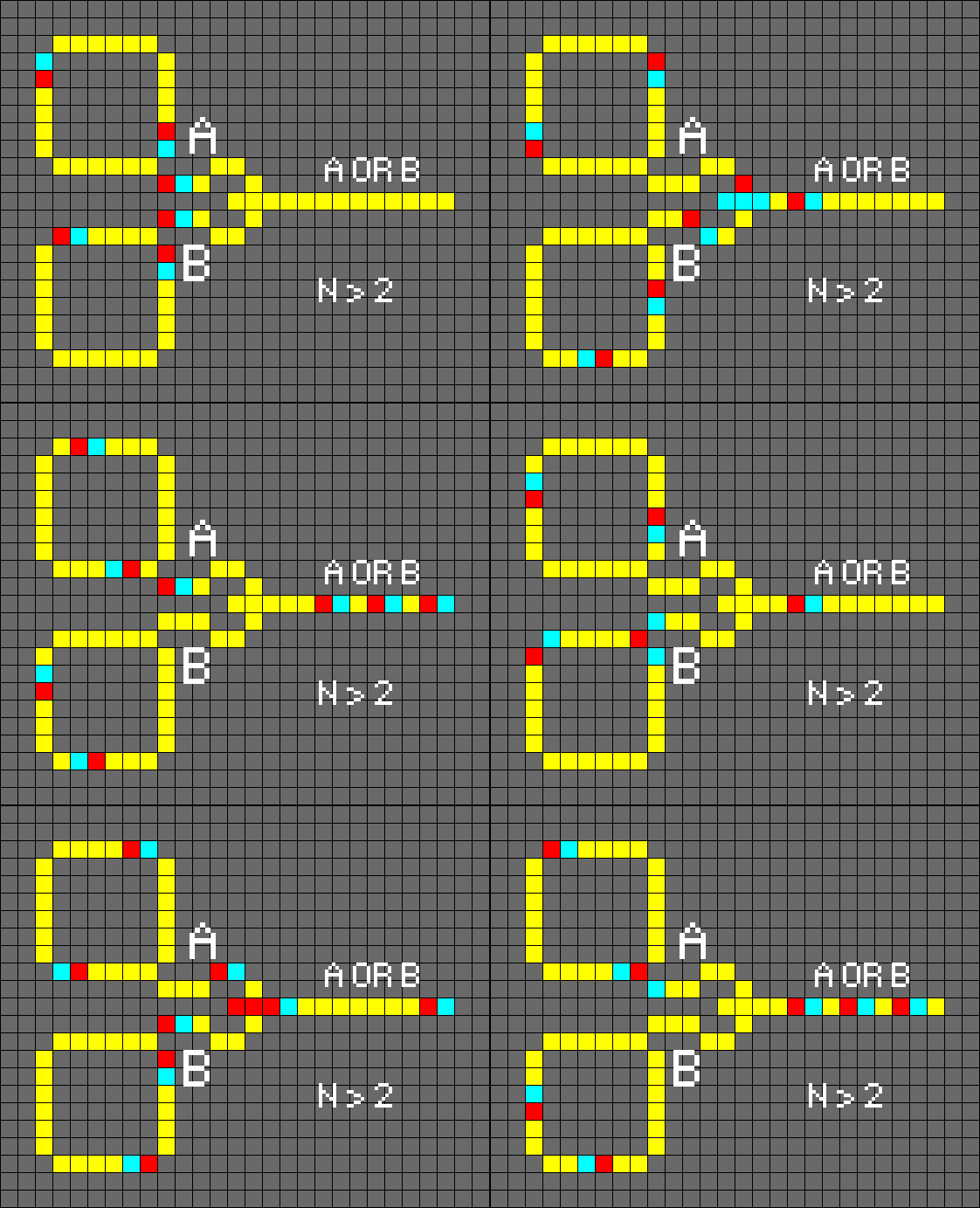
An OR gate emits an electron if there is an incoming electron at one of the two input wires.
XOR Gate:
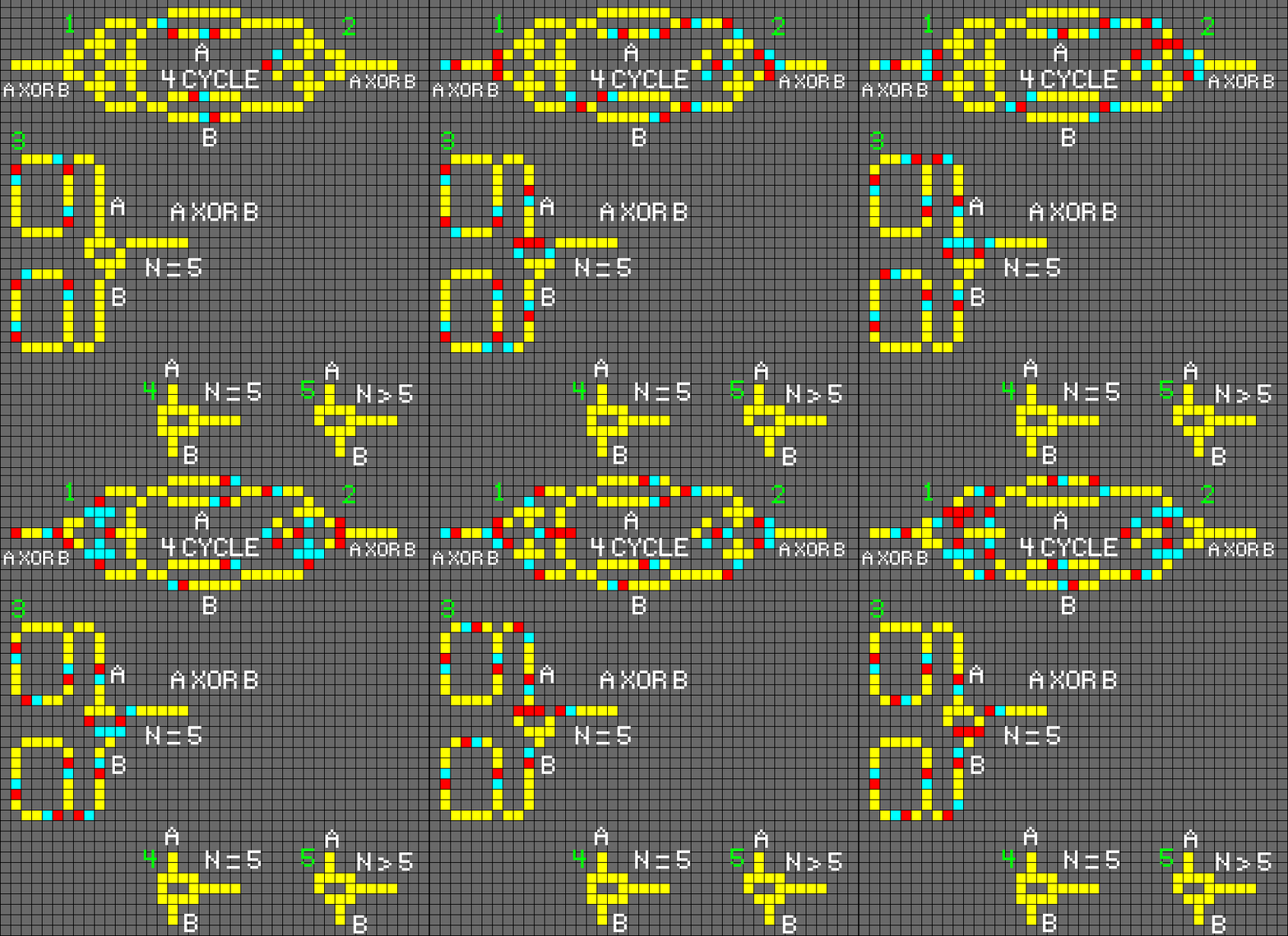
An XOR gate emits an electron if there is an incoming electron at one of the two input wires, but not on both.
EQUAL Gate:
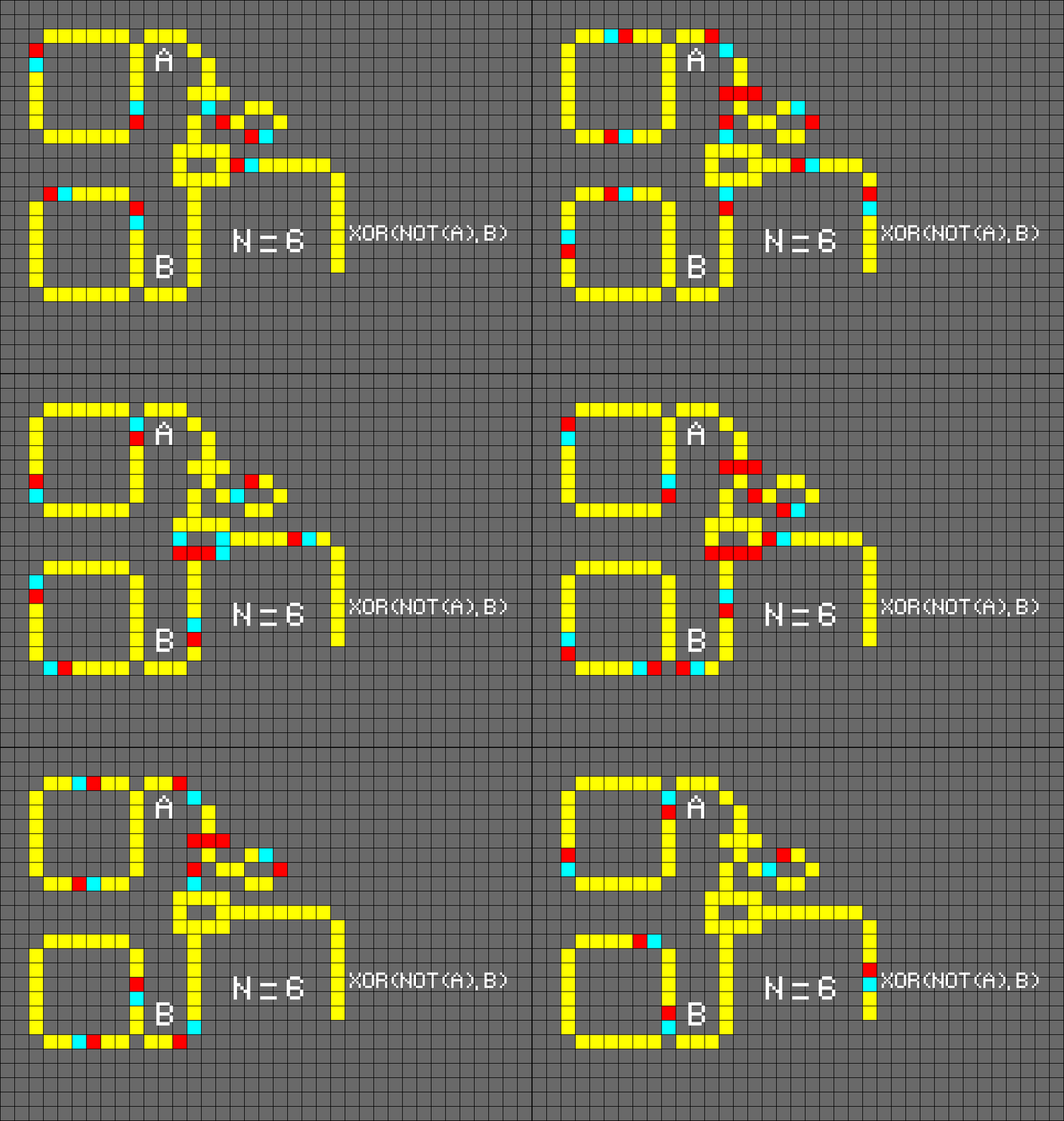
An EQUAL gate emits an electron if there are incoming electrons at both input wires and also if there is no incoming electron on either wire.
Useful Things:
Frequency Doublers and Halvers:
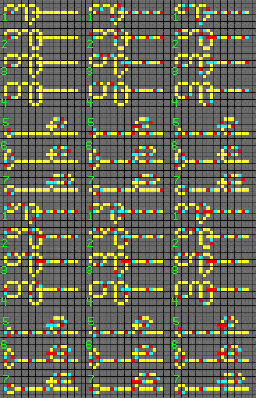
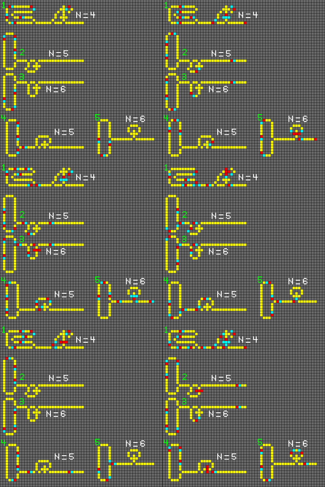
1-4. Frequency doublers
5-7 Frequency Halvers
Fuses:
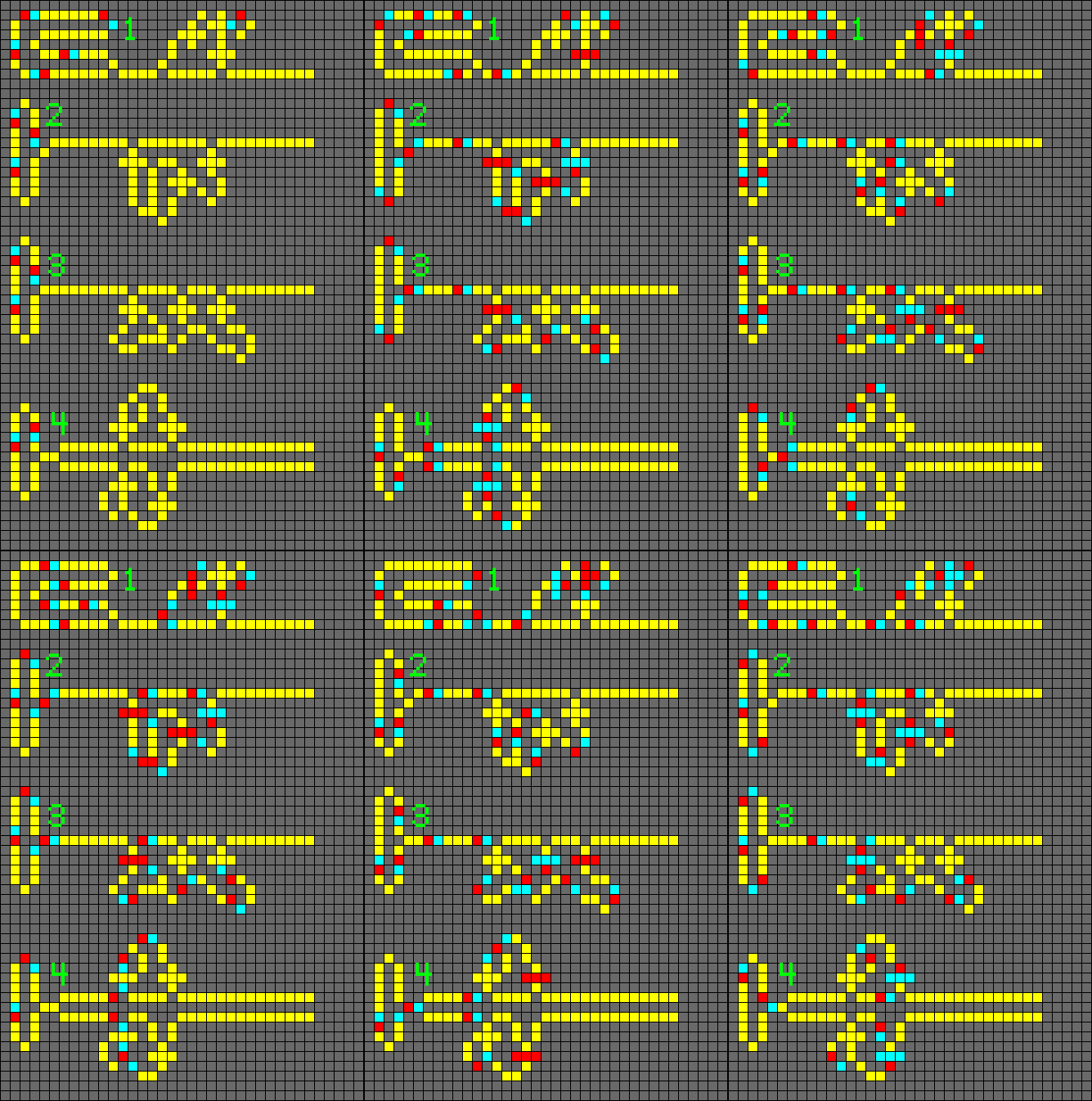
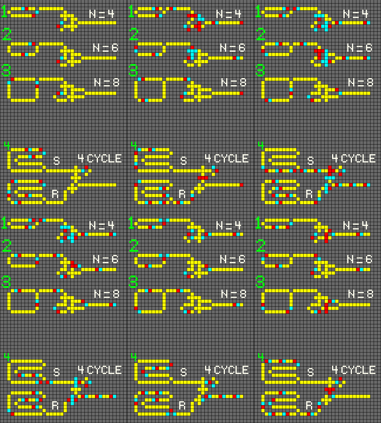
A signal to the fuse will cause it to stop all data flowing. Depending on how long the wire to the transistor (transistors) on the right is being fashioned, the data will stop only after a certain delay.
1. 4-cycle Fuse
2. 5-cycle fuses
3. 5-cycle fuses
4. Two 6-cycle fuses
Wire Crossings:
Memory:
ROM:
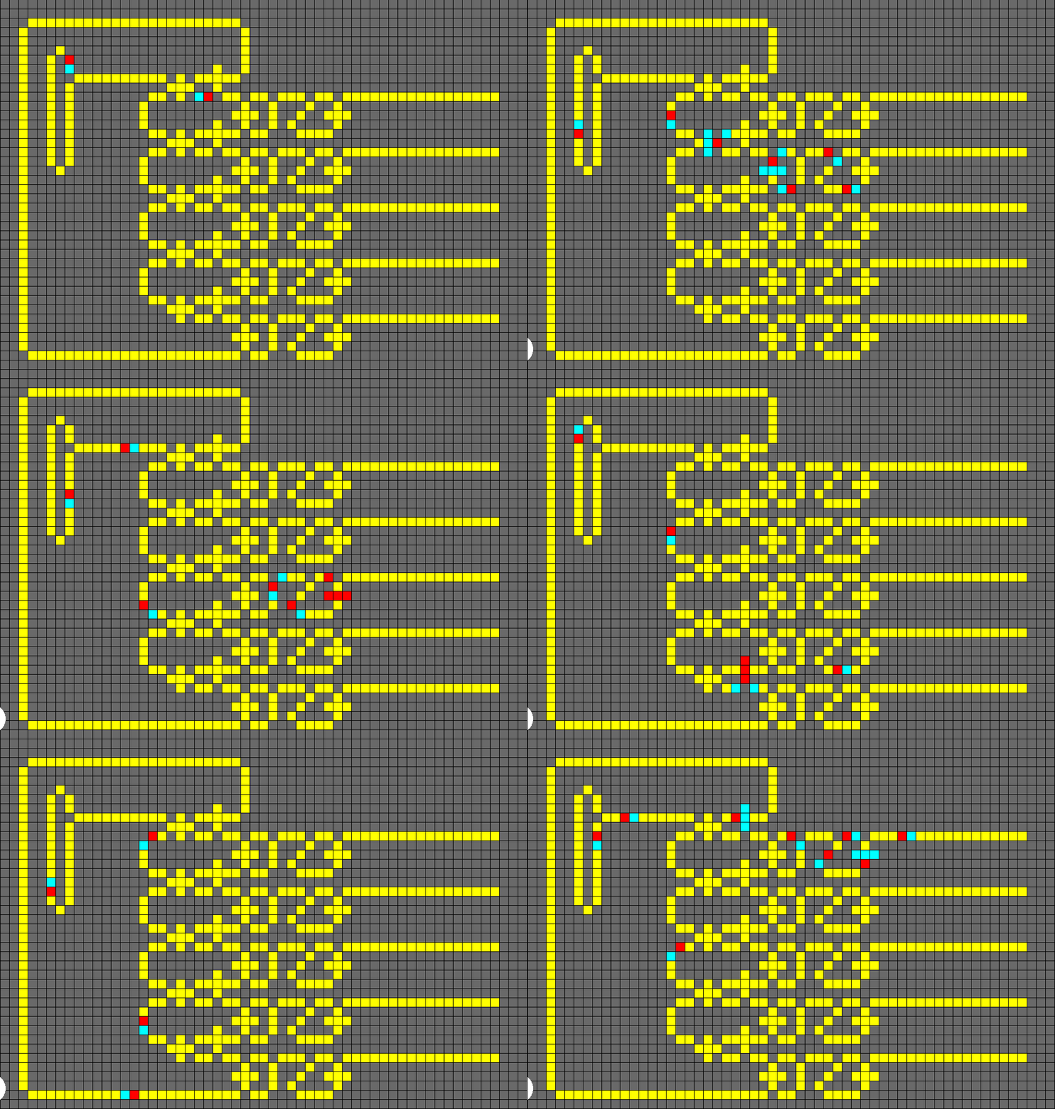
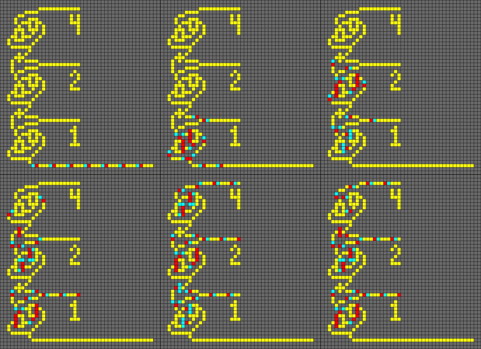
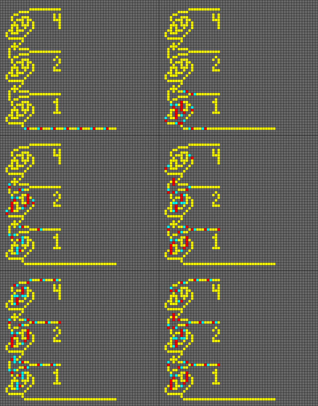
Several combined ANDNOT/OR gates can be arranged in a rectangular pattern to form a read-only memory. Here we have three input lines, each associated with four stored bits. The bits are those gates that have a missing 'ear'. An incoming electron moves toward the top right. Whenever the electron encounters a stored bit, it creates a twin. This twin then travels towards the bottom right, where it exits. Check how this corresponds to the missing 'ears' of the gates.
Flip-Flops, RS Latch:
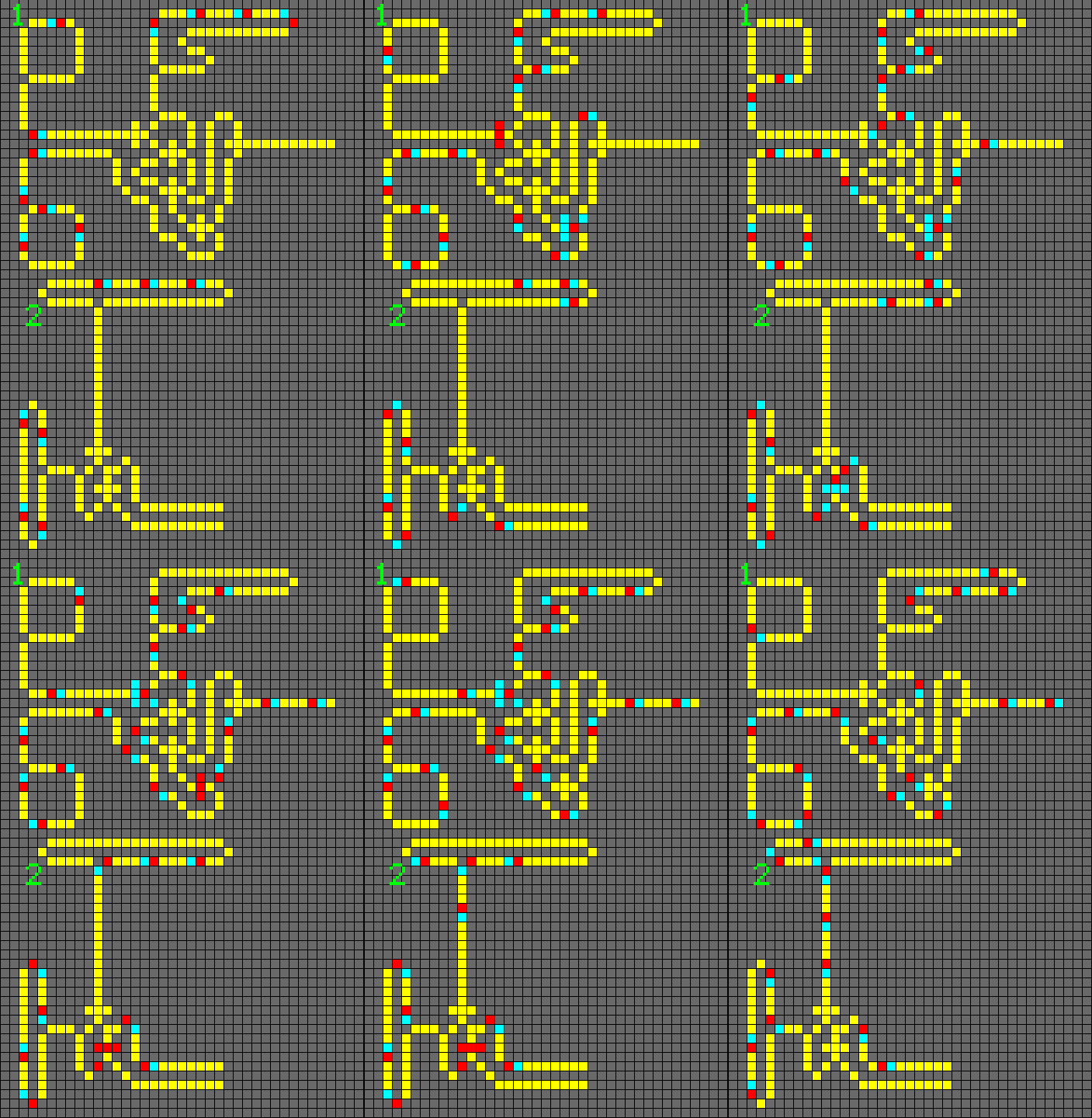
A flip-flop or latch is a circuit that has two stable states and can be used to store state information. It is the basic storage element in sequential logic.
Detectors:
Positive and Negative edge detectors:
A positive-edge detector emits a signal when it finds the first One (electron) in a row of Ones. A negative-edge detector emits a signal when it finds the first Zero (missing electron)after a series of Ones.
Switches:
Multiplexer, Demultiplexer:
A positive-edge detector emits a signal when it finds the first One (electron) in a row of Ones. A negative-edge detector emits a signal when it finds the first Zero (missing electron)after a series of Ones.
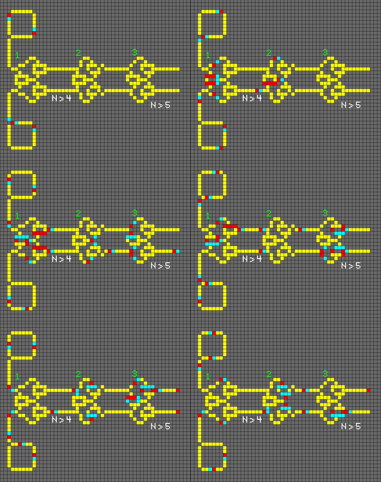
1. Multiplexer N > 4
2. Demultiplexer N > 4
Shift Register:
A shift register activates a series of memory cells one by one. A shift register is also called a 'serial to parallel converter' because the first signal is directed to the first output wire, the second signal to the second output wire, and so on
Mathematical Operations:
Binary Adder:
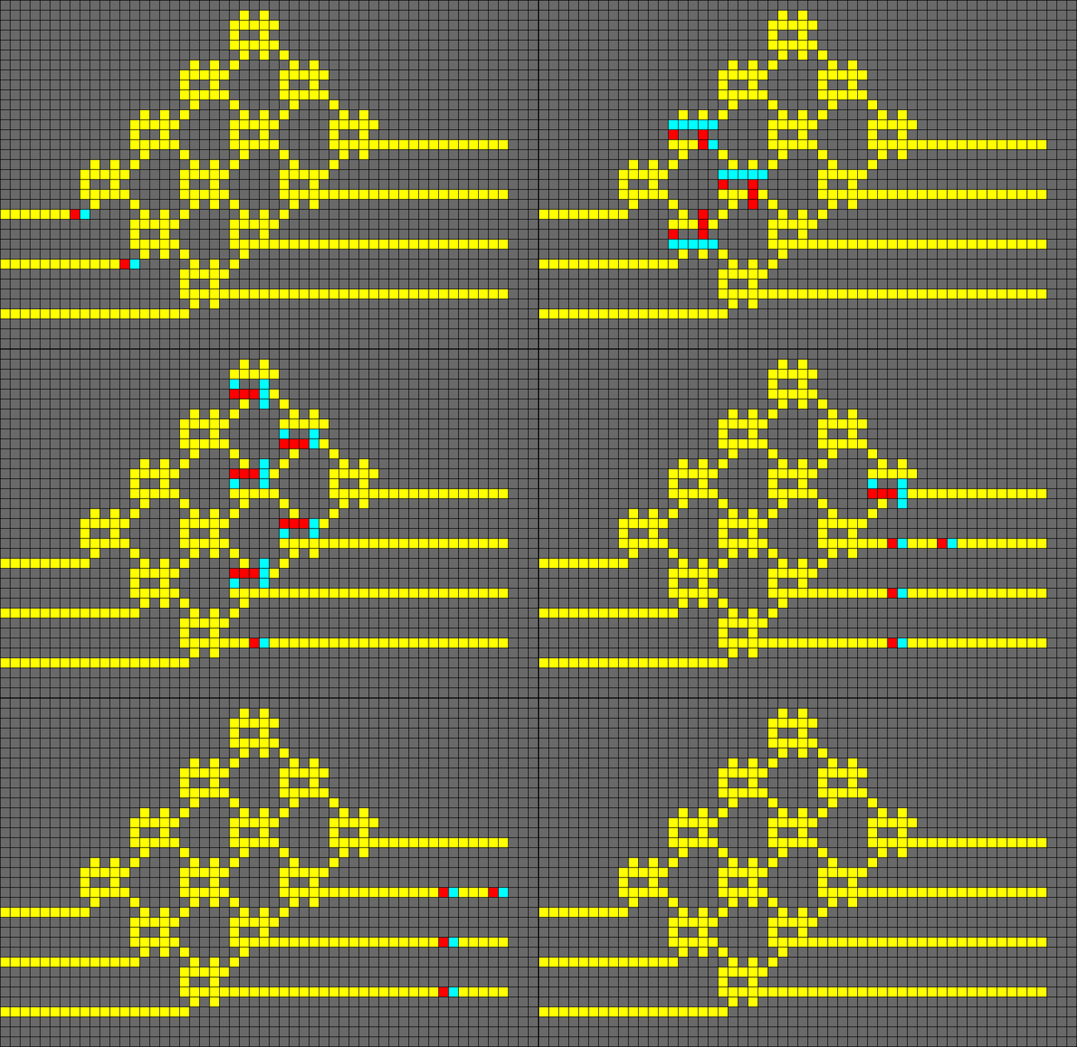
Input: one string of consecutive electrons representing a number Output: a series of active or inactive flip-flips, representing a binary number.
I do not own Wireworld nor did I come up with any of the components shown, but all code, art, and animations were done by me (Jakester).
Check Out:
https://en.wikipedia.org/wiki/Wireworld
https://www.quinapalus.com/wi-index.html
https://web.archive.org/web/20080124093712/http://karl.kiwi.gen.nz/CA-Wireworld....
https://content.wolfram.com/uploads/sites/13/2018/07/27-1-2.pdf
Source Code:
https://github.com/McCoy1701/Web-Wireworld
Gates Designed By:
Karl Scherer
Nyles Heise
Klaus Mogensen
Michael Greene
David Moore
Mark Owen
| Status | Released |
| Platforms | HTML5 |
| Author | Jakester |
| Genre | Simulation |
| Made with | pygame |
| Tags | 2D, cellular-automata, cellular-automaton, pygame, pygame-webasm, pygbag, python |


Comments
Log in with itch.io to leave a comment.
Very interesting automaton.